For a leading automotive supplier Ziemann & Urban delivered an end of line testing and adjustment system for 100% inspection of complex mechanical assemblies (engine hood hinges of a German Luxury Class vehicle). The safety-related component features an additional mechanism that lifts the hood via springs in case of a crash. This reduces the risk of injury to predestrians significantly.
The unit is working with different types of parts and is designed for mixed operation (right and left parts processed simultaneously). The turnkey system is designed as a clocked round plate system with manual loading and a total of 8 positions. The following process steps are performed automatically:
- inspection of completeness for installed components
- measurement of different characteristics (eg holes, openings, fixing points) in the 3D car coordinate system using image processing and laser triangulation
- Automatic repeated movement of the hinge to overcome the breakaway torque and subsequent measurement of operating forces
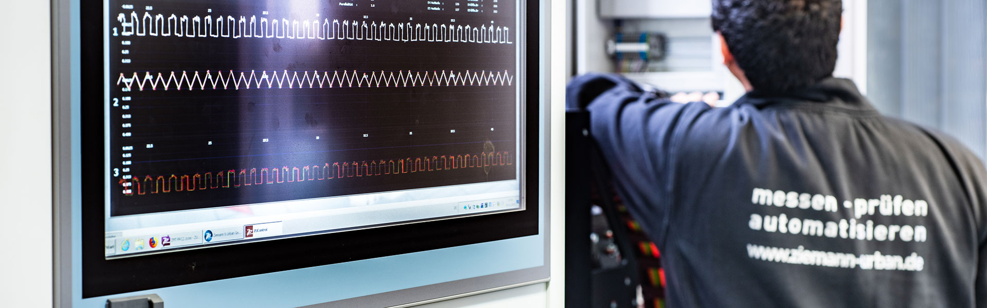
- operating of safety mechanism with measuremtn of the force-motion profile
- adjustement of a defined height dimension of the hinges with an automatic screwdriver unit an final measurement
- lifting of the hinges and clamping at the mounting points. Measurement of the reference points via vision system in the shell coordinate system to ensure the optimal mounting capability
OK parts get a printing on the upper plate of the hinge with an industrial inkjet printer. The print head can be moved by linear axes for all types and variants.
The inspected components are automatically placed in pairs on a conveyor belt. The extraction is performed with a 3 axis gantry with magnetic gripper. An integrated scales untig ensures that the hinges are always stacked in pairs in the transportation units.
NOK parts are stored on a separate rework conveyor belt. Those parts get a complete re-inspection and after a defined review process. Failure cause and location are visualized for the operator on a screen. This screen also displays the general operation of the system. All test results are documented in files on the system.
The inspection and sequence control is carried out on a 19" industrial copmuter. It is integrated into the machine frame. The cycle time of the system is approximately 20 seconds per part.
The system is declared as a measuring system in the production enviroment with a built-in verification mode for cyclic measuring equipment monitoring. It has been proven the capability to measure the necessary tolerances with measuring system analysis (MSA). The MSA is done with separate supplied calibration parts and defined error patterns.